![]() Return to TiltPlate page
Return to TiltPlate page
![]() Return to FAQs page
Return to FAQs page
DreamBeam36 W4QMC Lateral Strut Mount
Steve / W4QMC noticed his DreamBeam36 boom would flex laterally significantly in a breeze. This was causing the TiltPlate to lift and engage the KARLock when the wind was coming from the direction that normally would push the plates together.
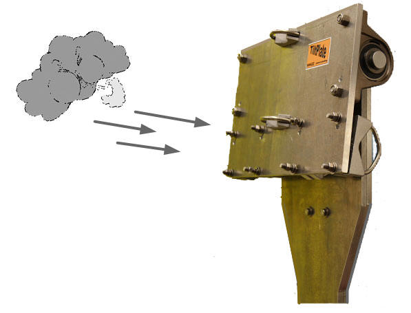
This lateral boom bend was causing a weight imbalance due to the heavy trombone elements on the DreamBeam36. The weight imbalance in turn causes the TiltPlate to lift and lock the KARLock. When the wind subsides the weight keeps the KARLock engaged. Apparently the bending is only an issue in that one direction.
You may not have the problem or Steppir may have fixed this issue with a stronger or different boom. But If you do have the problem, here are 3 options to consider.
1) You can add a lateral boom truss using standard parts from DXengineering (Boom plate, 2 inch tube and cables). The plate and tube would be mounted to the either side of the TiltPlate and the tube would be next to and parallel with the trombone elements with the cables attaching to boom about 8 feef on either side. Although the support is only needed on the "moveable plate" side, you could use a 6 foot tube and support both sides.
2) DXengineering sells a boom truss designed to provide lateral support. This has not been tested with the TiltPlate but you may be able to mount it next to the TiltPlate or on the outside of the trombone. It does not have to be perfectly centered over the TiltPlate to work.
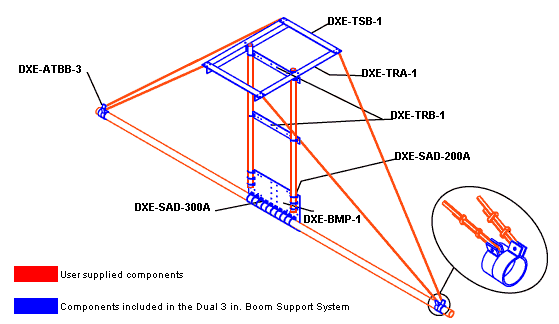
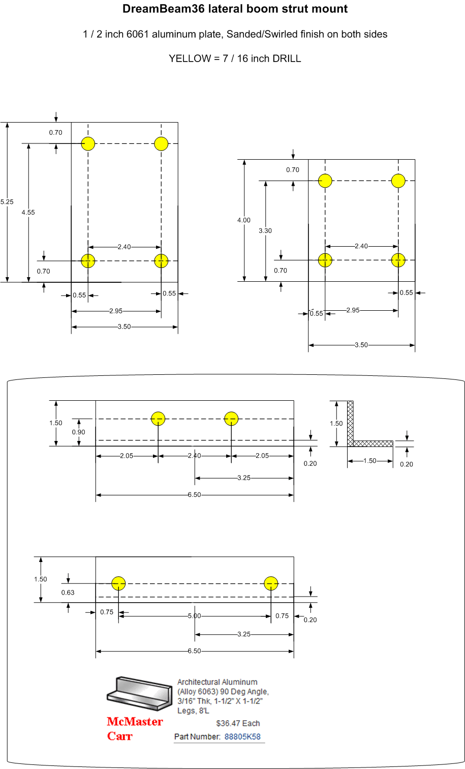
3) Add a truss mast support that mounts directly to the TiltPlate. Below is the diagram that for a lateral truss mount I made for Steve. You can make it yourself of I'll provide one for my cost which is $123. See parts and price breakdown below. Email for more info and ordering.
Comment from Jeff / W0JM. "...I fabricated a support using your measurements as a guide." Click here and scroll down to Jeff's installation pictures
Comment from Steve - "...this mod DOES solve the problem conclusively ! As soon
as the weather clears, I will get you the pics. " (I
will add Steve's pix when I get them.....)
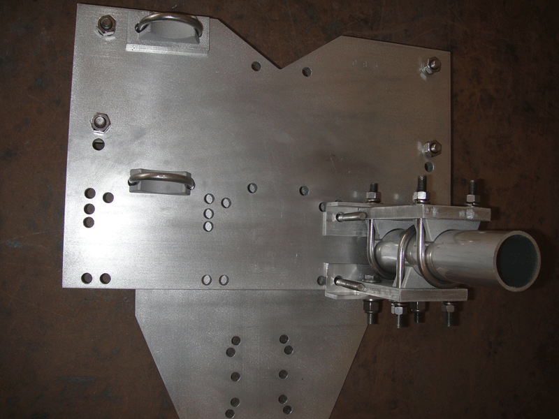
The tube shown above is just for illustration. You would need to provide a 3-4 foot 2" tube for the actual installation.
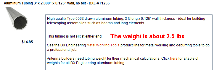
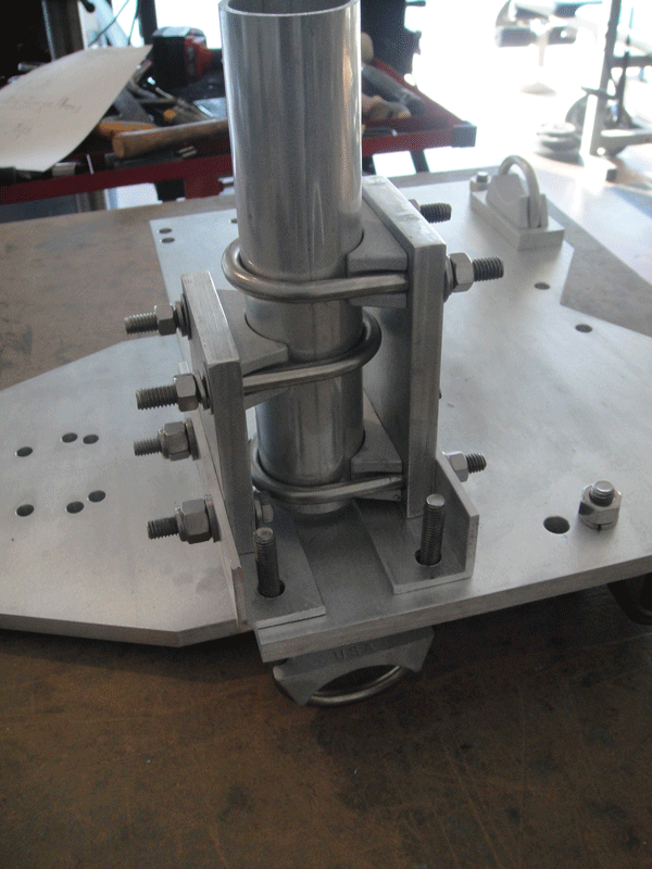
The tube shown above is just for illustration. You would need to provide a 3-4 foot 2" tube for the actual installation.
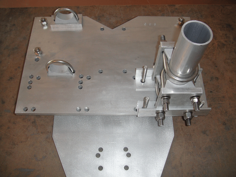
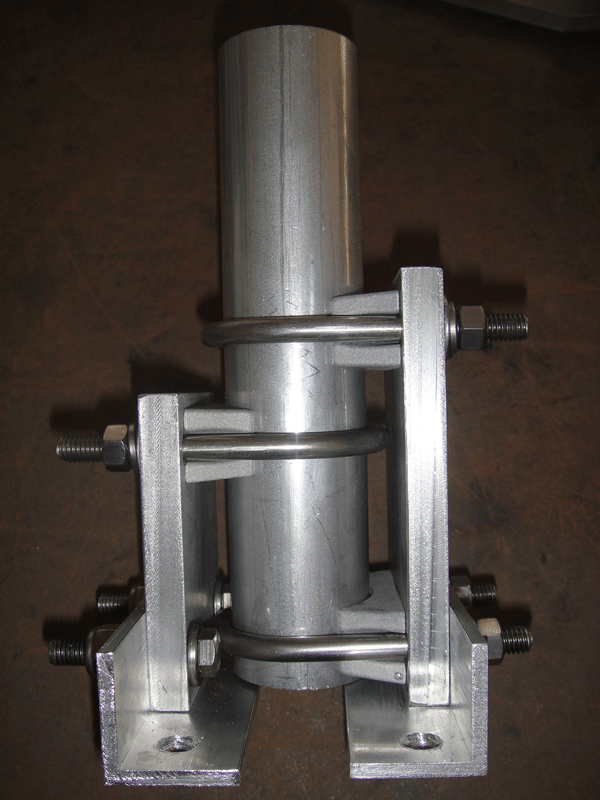
Diagram to make your own
2 inch U-bolts, DXE-SAD-200B from DX Engineering
Approximate Cost for Materials